
This is the fourth part of a six-part post:
Part 1: System design and planning
Part 2: Circuit and PCB design
Part 3: Mechanical design
Part 4: Firmware
Part 5: Installation and external power
Part 6: Conclusion, problems and screwups
Basic architecture
Incoming events trigger external interrupts. The handlers post the event details into a queue. The events are:
- Button press/release
- Proximity detect
- RTC minute tick
- RN52 GPIO2 event (i.e. RN52 state change)
A simple control loop pulls events from the queue and dispatches them to various handlers (within the same execution context). The same loop updates the display, manages the display brightness, and puts the MCU to sleep when inactive.
Graphics
Text
I have previously written bitmap font rendering code, which is included in the Libpekin library.
For this device, I used a single font for the UI - 14pt Roboto Condensed. It's available under the SIL Open Font License. To render the TrueType version of the font to a bitmap suitable for use with the library (i.e. as a Libp::RasterFont object), I use andryblack's Fontbuilder tool, Imagemagick, and a Python script.
The Fontbuilder program is used to generate a BMFont file and a PNG image containing the glyphs.
The script then:
- Reads the BMFont configuration file.
- Invokes ImageMagick to convert the PNG into raw pixel data in a specified bit depth (2-bit in this case).
- Writes a C++ header file defining a
Libp::RasterFontobject for the font, complete with all of the data needed to display it.
Example output from the Python script:
//
// Raster font
// -----------
// face  : Roboto Condensed
// size  : 14
// bold  : 0
// italic: 0
// smooth: 1
// bpp   : 2
// chars : 32 -> 126 [ !"#$%&'()*+,-./0123456789:;<=>?@ABCDEFGHIJKLMNOPQRSTUVWXYZ[\]^_`abcdefghijklmnopqrstuvwxyz{|}~]
//
inline constexpr uint8_t roboto_cond_14_2_raw_img_dat[] = { // 4392 bytes
    0x00, 0x00, 0x00, 0x00, 0x00, 0x00, 0x00, 0x00, 0x00, 0x00, 0x00, 0x00,
    0x00, 0x00, 0x00, 0x00, 0x00, 0x00, 0x00, 0x00, 0x00, 0x00, 0x00, 0x00,
    0x00, 0x00, 0x00, 0x00, 0x00, 0x00, 0x00, 0x00, 0x00, 0x00, 0x00, 0x00,
    ...
};

inline constexpr Libp::Image2d roboto_cond_14_2_img = {
     732, 24,
     Libp::Bpp::msb_2bpp,
     roboto_cond_14_2_raw_img_dat
};

inline constexpr Libp::CharMeta roboto_cond_14_2_meta_data[] = { // 95 entries
    // x position, y position, width, height, xoffset, yoffset, xadvance
    { {0, 17}, {0, 0}, {0, 18}, 4 }, // ' '
    { {0, 3}, {3, 14}, {1, 4}, 5 }, // '!'
    { {3, 3}, {5, 4}, {1, 4}, 6 }, // '"'
    ...
};

inline constexpr Libp::RasterFont<32, 126> roboto_cond_14_2(
    roboto_cond_14_2_img,
    roboto_cond_14_2_meta_data);
Animations and transitions
One of the key requirements of the project was to have some interesting animations on the display during pairing, playing etc.


Knowing close to nothing about how animation is typically structured in code, I settled on what seemed to work from first principles. Each animation is encoded in a single function. The functions are passed an animation context, which gives them the current frame, time, etc. and a surface to draw on.
The display code maintains pointers to active animations, and upon notification of state changes, switches animations by reassignment, with up to two animations running simultaneously.
This yielded a pretty simple architecture using minimal resources. I imagine there are far better ways to accomplish the same thing, but as with most embedded projects, it doesn't pay to develop an abstracted, extensible API for a one or two-time project.
The animation functions use combinations of bitmaps and primitives drawn using the Libpekin drawing code.
The images used in the animations were created using the following workflow:
- Draw images using Inkscape
- Export to PNG
- Convert to 4-bit raw data using Imagemagick:
magick cat.png -depth 4 gray:cat.dat - Convert raw data to C source:
xxd -i cat.dat > cat.h

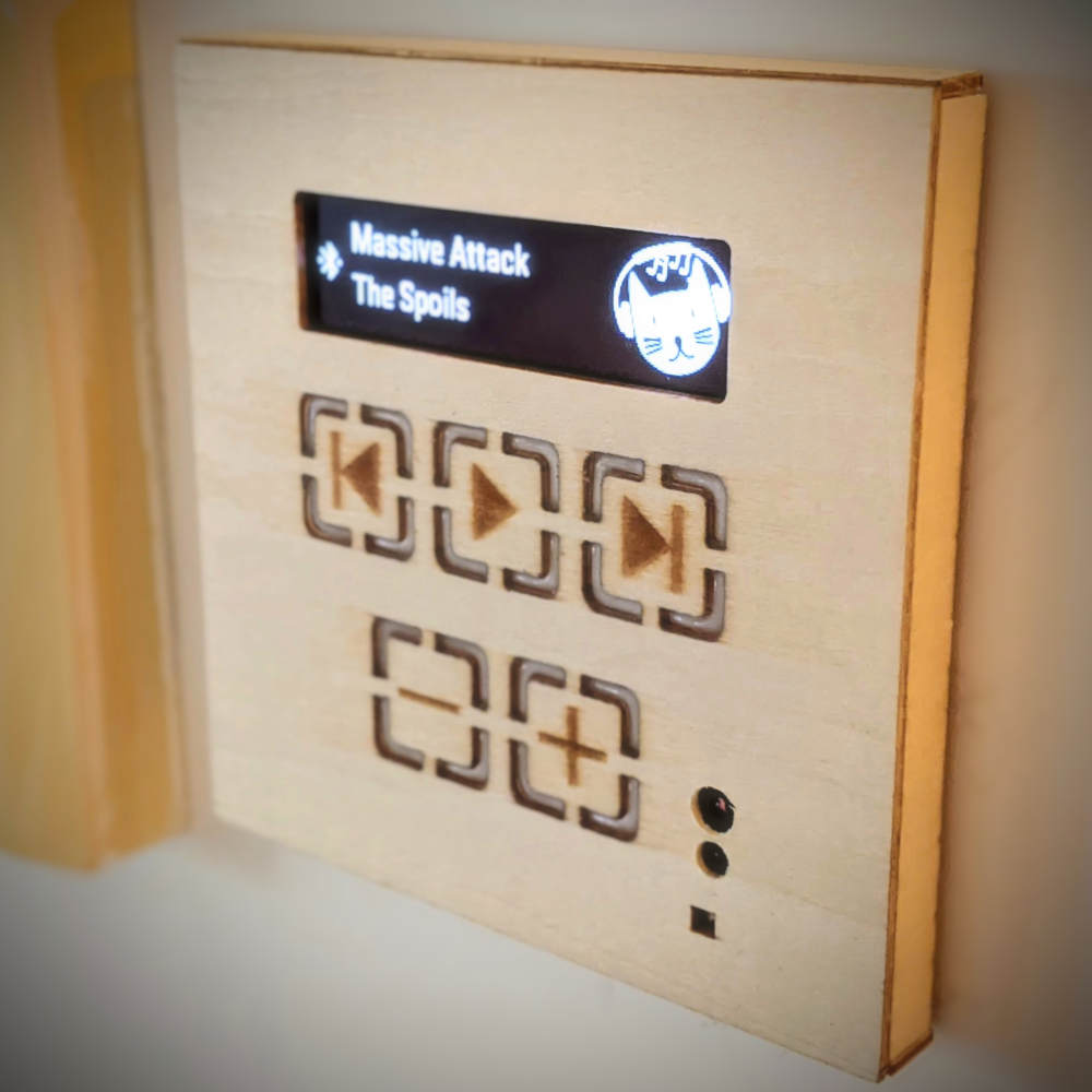
I can't recommend the RN52 :-(
Testing and development of a driver for the RN52 revealed a few issues:
The firmware is pretty awful
There are a number of issues, but biggest is the poorly thought out track notification functionality.
When the module changes state (e.g. new device connected, audio started streaming etc.), it pulls GPIO2 low for 100ms. The idea is that this is detected via an MCU external interrupt and the controlling MCU can then issue the Q command via the UART to determine the cause of the event and the new state. This works as expected.
But what if we want to get a track change notification? No problem, we just set the appropriate bit in the extended feature configuration and voila, GPIO2 events are now triggered on track changes. We can query the status via the Q command and see that the "track_changed" bit is set, and then issue the AD command to retrieve the new track metadata as required.
At least that is how it should work. Instead, on track change, after triggering a GPIO2 event, the RN52 simply outputs various metadata fields over the UART.
This is a significant problem. If the Q command is issued after a GPIO2 event, sometimes the data subsequently received will be the status code (which is the expected result of the command), and sometimes it will be preceded by (or mixed with) an unknown length of metadata. We can read past the metadata first before issuing the Q command, but it is typically not present and when it is, can be delayed by up to 300ms.
Even if we are willing to delay event processing by 300ms, we're liable to receive the metadata in the middle of other commands such as changing volume etc., which leads to the command seemingly failing because we do not receive the expected AOK confirmation.
We could ignore anything received over the UART unless we have issued a command, but even that risks the chance of receiving the metadata during the process. There seems to be no way to enable GPIO2 event notification on track change, without also receiving the random metadata output over the UART.
Track metadata was added in a firmware revision and clearly was not fully thought out.
I contacted Microchip support about this, and was able to confirm that it is indeed a firmware issue (and unlikely to be fixed given the device is no longer recommended for new designs). I must point out that despite the dodgy firmware (which I believe was developed by another firm and then acquired), Microchip provided an outstanding level of support investigating this issue.
I managed to mitigate the issue by filtering all of the RN52 UART output and throwing away lines of metadata received except when it was explicitly requested. For anyone with similar issues, the mitigation can be found in the driver.
Limbo mode

The command reference document describes the Limbo state as "logically off but physically on". And that is the extent of the discussion. There is no other mention of it in the datasheet or associated docs. Did I mention that the datasheet/command reference is far too thin?
I am not the only one: https://www.microchip.com/forums/m843189.aspx
The device entered this state a few times during testing. Once in the state, it's still possible to communicate with it over the UART, but it is no longer connectable over Bluetooth. There is no information on how the device might end up in this state and the only way to exit it appears to be a reboot.
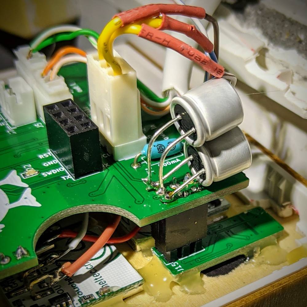
Some in-depth testing revealed that the likely cause was a very brief (microseconds) Vdd drop (to ~2.9V) caused by the proximity sensor LED lacking sufficient local decoupling and the supply coming over several meters of Cat5e (both entirely my fault). The typical response to an event like this is a brown out reset, which provides a good indication that something is wrong on the supply side (possibly even with the help of a pre-reset interrupt). Shifting into an undocumented mode instead was not expected.
The issue wasn't helped by Microchip hosting an old datasheet on their site (first Google search result for "RN52 datasheet") that stated the operating voltage of the RN52 was 1.8-3.6V. I had (incorrectly) assumed that the device would function correctly across that range and that there was sufficient decoupling on board the module itself to mitigrate noise on the supply rail.
The latest datasheet (correctly linked from the Microchip device page) shows the operating range of the current version of the module is 3.0 - 3.6V. The addition of 2000µF of low-ESR capacitance to the supply on the proximity sensor board solved the issue.
Volume control via S/PDIF
The volume control of the S/PDIF digital output is very jumpy. Adjusting the volume of a digital audio signal is challenging and will always result in some distortion given limited resolution, but the RN52 provides about 3 volume steps (off, quiet, or full) over the entire 25-step range of the phones tested.
Other Drivers
Ambient light / proximity sensor (VCNL4200)
I was unable to locate any public drivers for this part, so built my own. The proximity sensor is configured on startup to generate an interrupt whenever the proximity count exceeds the baseline level plus a buffer. The baseline is measured on startup after configuration.
The ambient light sensor is polled in the main program loop to adjust the display brightness.
The device has various configurable parameters including sunlight immunity adjustments, but I found none were necessary for this application.
Humidity/temperature sensor (BME280)
Bosch helpfully provide a C driver for the BME280. I've used it before and it works well, but is reasonably large. I wrote a small 32-bit integer version (the Bosch driver can be configured for 32/64-bit integer or float math via macros) for another resource-constrained project and am using that here. It saves about 1k of flash and ~30 bytes of SRAM in an optimized build.
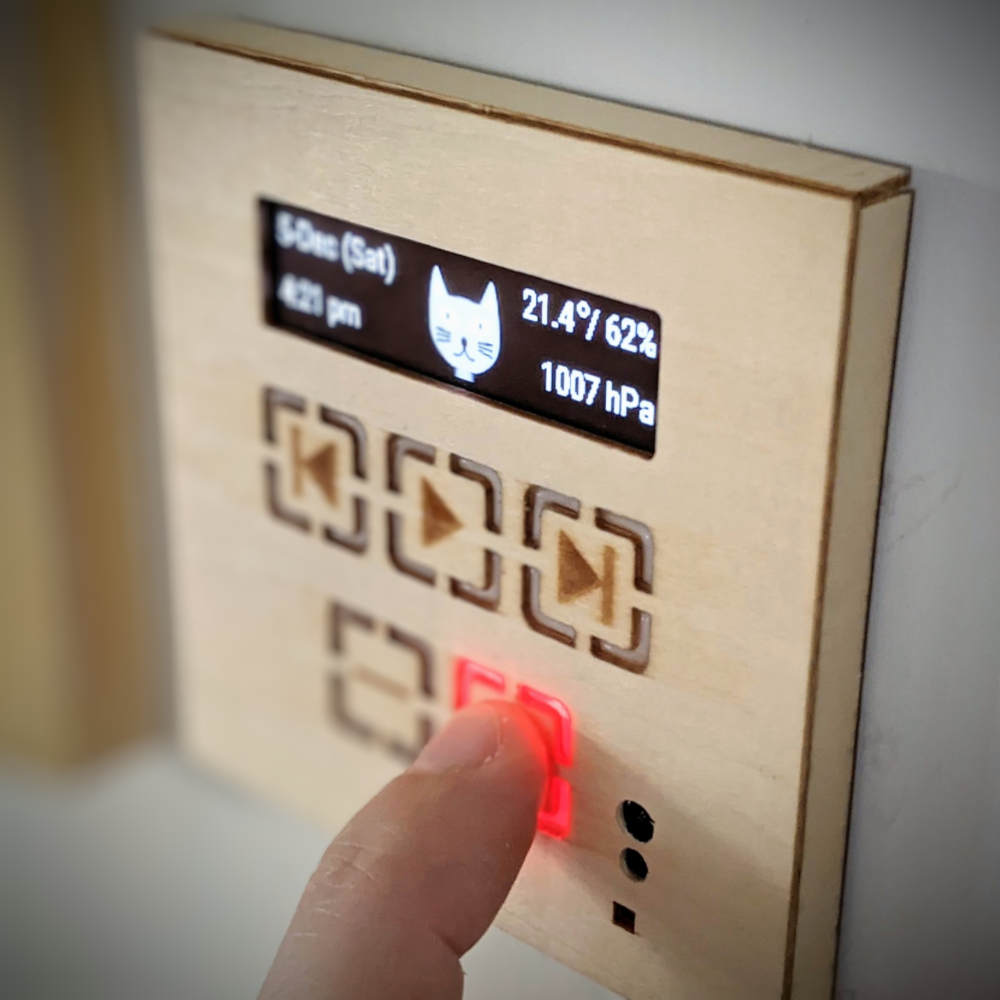
Real-time Clock (RV-8803)
I wrote a driver for the RV-8803 as I intend to use it in future projects. The device is configured on startup to fire an external interrupt every minute, which triggers a redraw of the screen if the device is not sleeping. The media and volume buttons are used for clock setting, which shouldn't be required very often given the accuracy of the RV-8803.
OLED (SH1122)
The SH1122/SSD1362 drivers are quite simple. Since there is sufficient SRAM on the MCU, we're using a full display buffer in SRAM for drawing operations and then flushing to the display. The drivers therefore only need to support a full buffer write command.
The only additional complexity is brightness control. I abhor super bright displays at night - which is the reason for including the ambient light sensor - so brightness control is needed. The SH1122 has a contrast command supporting 256 levels, but even at it's lowest level, the brightness is not much reduced.
Pre-charge to the rescue
Some searching online revealed those that had had success lowering OLED brightness further by modifying the precharge levels.
I know little about the analog side of OLED electronics, but as I understand things, OLED pixels are driven with high currents initially in order to quickly get the voltage across the LED up to the level where the pixel will light (this isn't instant given intrinsic capacitance). After that it can be driven by a constant current. Presumably the pre-charge level register varies the voltage at which this switchover occurs.
For the SH1122, setting the segment precharge level in combination with the contrast was very effective at providing a much wider range of brightness levels.
MCU speed
I did the main development with the STM32F103 running at 72 MHz. Once complete, I reduced it down to 32 MHz without issue. The only speed sensitive code ares are the animations and ensuring that the UART receive buffer doesn't overflow.
The Final Firmware
The final build is ~42kb using 9kb of SRAM. 8kb of that is the display buffer. The full code will be put on github and linked here shortly.