
This is the third part of a six-part post:
Part 1: System design and planning
Part 2: Circuit and PCB design
Part 3: Mechanical design
Part 4: Firmware
Part 5: Installation and external power
Part 6: Conclusion, problems and screwups
Mechanical design
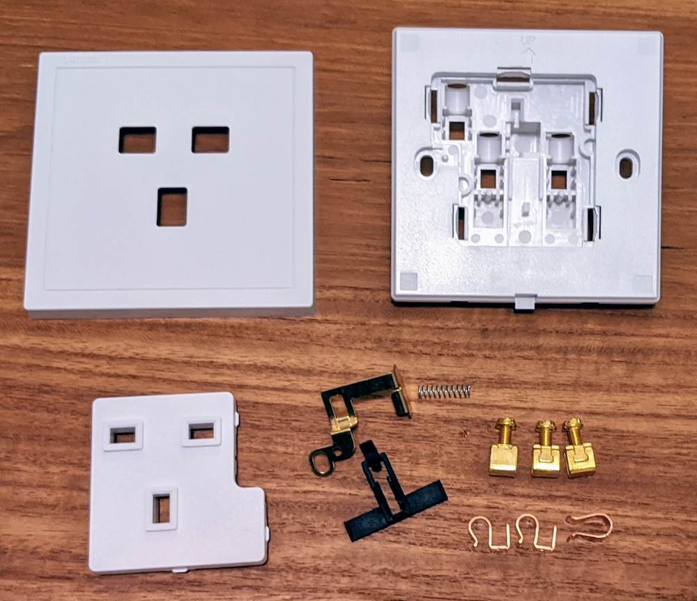
The most difficult aspects of the design are mechanical. Fitting the module into a standard electrical junction box (AKA back box) without visible fasteners, while allowing for it to be easily removed and look good is quite a challenge.
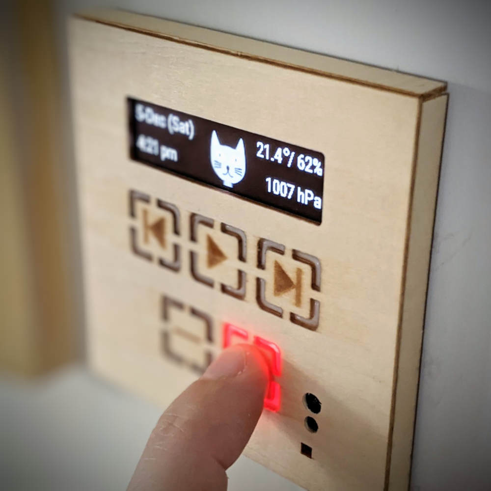
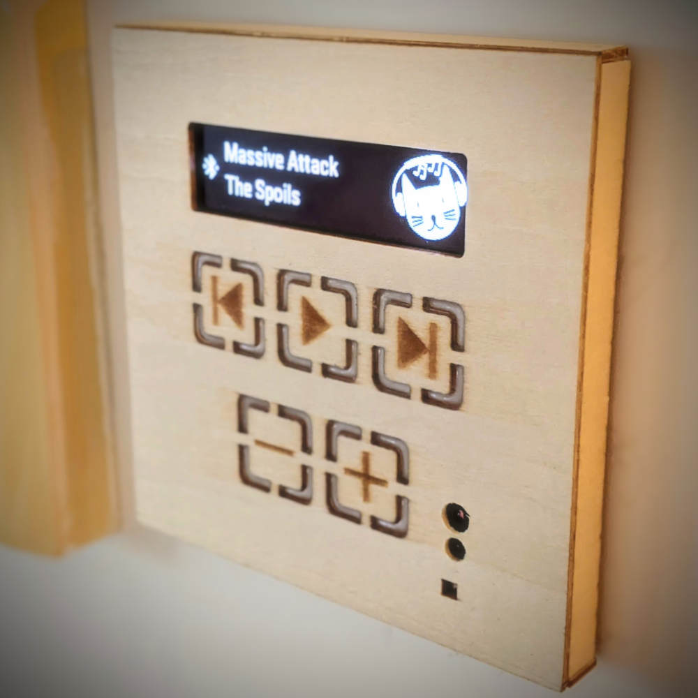
To get a professional looking finish at a reasonable cost, I'm using a thin, laser-etched wooden facade placed on top of a cheap electrical socket shell. A small white OLED screen will feature at the top, and capacitive touch sensors will be placed behind the wood for control.
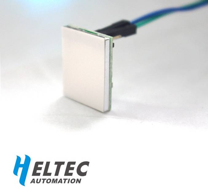
I had previously played around with these [PDF] pre-built capacitive touch buttons and knew them to be sensitive enough to work behind a millimetre or so of wood. They include colored LEDs that glow when touched, and so by etching all the way through the wood in parts and filling the holes with casting resin, a pleasing visual feedback mechanism should be possible.
Update:
I can't recommend these capacitive buttons, as one has failed after around 3 months. Hopefully it will be the only one. Will update here if more go.
Laser-etched wood facade
Having never used casting resin or laser-etched wood, it was a bit of a learning experience. The laser cutting service that I used offers only one wood type (椴木), with a minimum thickness of 1.5mm and 880x440mm sheet size. Given the large sheet, I prepared a few different designs.

The results were pretty good, given the price point (~US$6 for 16 facades - could have been 32, but I only used half of the wood to reduce shipping costs). The wood itself is very light, but should be strong enough for the application. I believe the typical use of the service is for building 3D architectural models, so it seems appropriate.
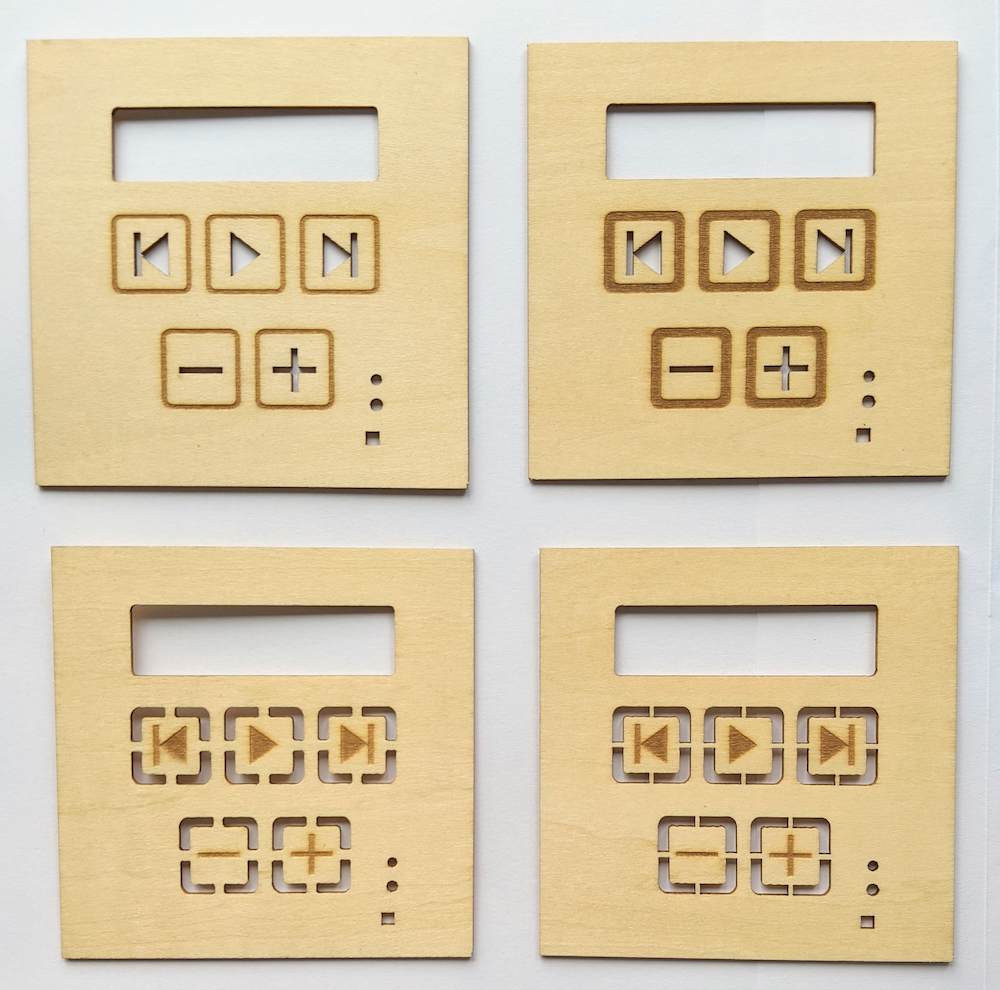
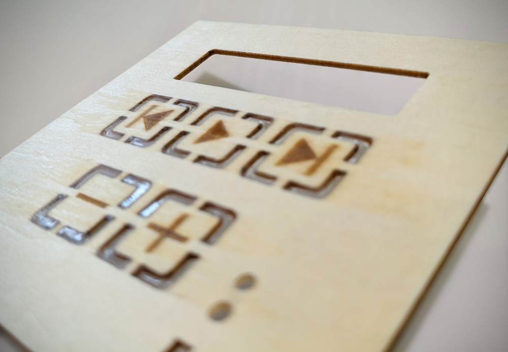
The burn marks could be a bit more consistent and sharp, but overall I was quite pleased.
Filling the gaps with casting resin
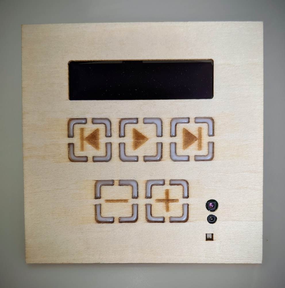
To create a flush surface and diffuse the glow from the lit buttons behind the wood, the gaps needed to be filled. After some experimentation, I determined the best method to be sealing the front with packing tape, laying the wood face down, and filling from the rear side.
I toyed with the idea of filling the screen area also, but was concerned about clarity and reflections.
Mounting the facade to the PCB
The light and proximity sensor needs to be flush against the back of the wooden facade. The BME280 sensor needs to be isolated from potential heat sources and ideally have external air flowing over it.
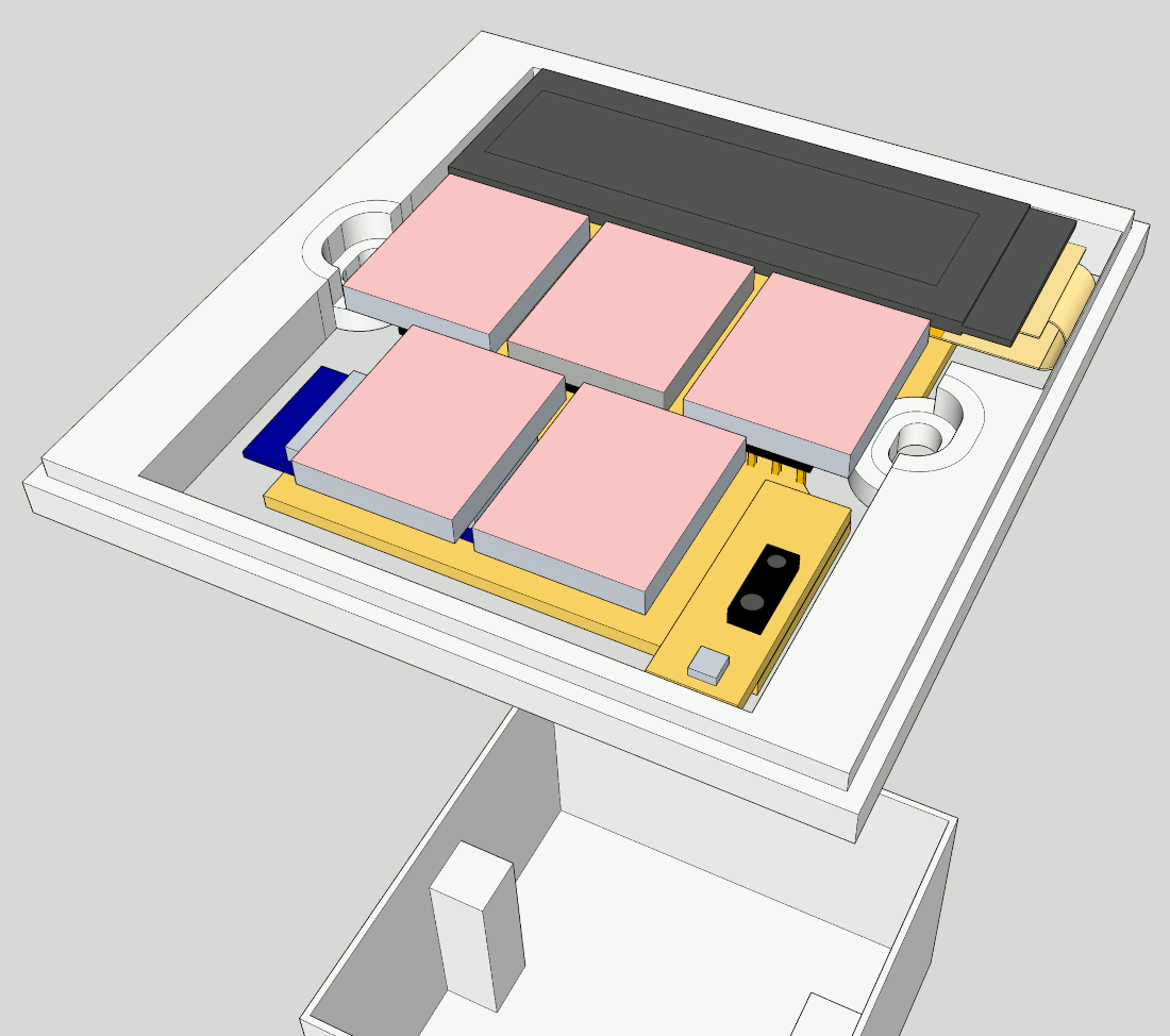
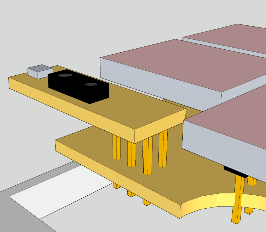
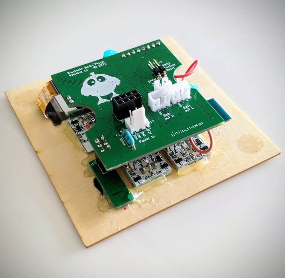
Unless we solder jumper wires directly to the BME280/VCNL4200 pads, these two requirements necessitate a second PCB containing these sensors to be attached to the main PCB (i.e. a daughterboard). If mounted on the main PCB, the height of other components (e.g. crystal) would result in the sensors sitting too far behind the facade. The daughterboard will be attached to the main PCB using a soldered 2x3 2.54mm pin header.
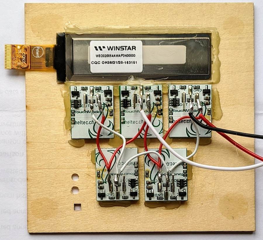
The touch buttons come with a standard 2.54mm, 3-pin header. The original idea was to put 3-pin female sockets on the PCB in the locations corresponding to the buttons, glue the buttons to the facade, and just plug the facade onto the board. That would have made the bottom half the PCB mostly unusable given the socket locations. Consequently the BT module would need to be mounted at the top of the board, behind the OLED screen. Given the amount of metal in the screen and the proximity to the module's antenna, this would likely have impacted the range too much.
So I instead decided to bend the pin headers on the capacitive buttons 90 degrees, and use jumper wires to connect them to a single pin header on the PCB. This allows the BT module to be mounted at the bottom of the PCB, with greater clearance around the antenna, as well as simplifying the routing and giving more board space for the other components. Fixing the facade to the PCB will also be more forgiving, as the OLED FPC connector, button sockets, and light sensor sockets no longer need to be perfectly aligned
edit: the FPC connector still requires perfect alignment given the position requirement for the proximiy/environmental sensors - it was a very tight fit.
The antenna location is still not ideal given the proximity of the capacitive buttons, but there are no perfect options here (edit: The range turned out to be no concern, with a stable connection from clear across the house).
The OLED FPC connection at the top left is very close to not reaching.